
Lávka Holešovice-Karlín

CONCEPT AND LOCATION
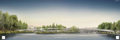
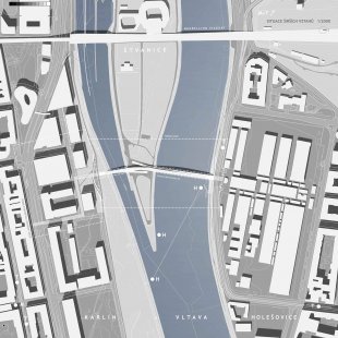
At the place where the Vltava River washes the island of Štvanice and flows north towards the branching arms under the Libeň Bridge, it passes two significant districts – Holešovice and Karlín. The river flows under the arches of dozens of historical bridges, whose intersections inspired the design of this footbridge.
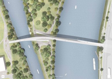
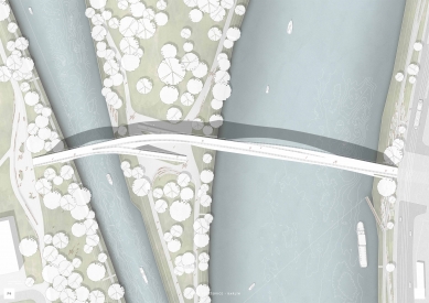
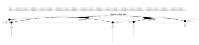
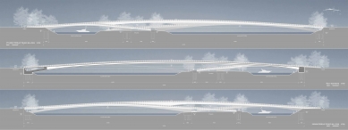
The design expresses humility towards the panorama that forms the city's identity: its lines are simple and modestly remain low above the horizon. However, it stands out with uncompromising engineering skill, allowing for a structure as slender as if it were just the imagined trajectory of a thrown pebble above the water. A single continuous arch spans the entire width of the riverbed, ensuring the structure’s resilience against floods. Neither this nor the two additional arches, transitioning into the pathway on Štvanice, disrupt the water flow.
We utilize the full potential of 21st-century engineering to make the arches as slender and flat as possible, ensuring the bridge ranks among the best contemporary structures in Europe.
URBAN AND LANDSCAPE CONTEXT
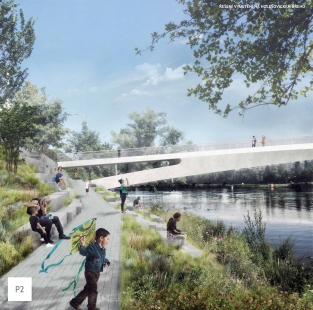
On the Holešovice side, the bank is reinforced against flooding with massive stone steps alongside dense native vegetation, returning to a more natural habitat and gently outlining the harsh environment of Holešovice with friendly greenery. Residents will be able to comfortably descend from the road level of the embankment directly to the river and to the HolKa P7 ferry stop.
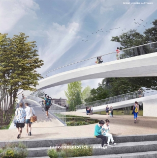
We attribute an equal role to the island of Štvanice. Along the elegant arch of the footbridge to Karlín, a pair of arches on Štvanice slope down to the island using ramps with a gradient of less than 6% for very easy barrier-free access.
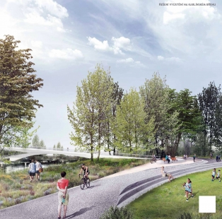
In Karlín, the footbridge leads into a smaller park sensitively designed among mature trees, creating an ideal meeting place for families and friends. At the same time, it connects to pedestrian pathways toward the interior of the district.
BRIDGE STRUCTURE AND STATIC SOLUTION
The dimensions of the supporting structure arise from the proposed static scheme and load-bearing requirements. The supporting structure consists of two main supporting flat arches with a hollow cross-section made of reinforced concrete. The arches are directly walkable at the apex. The central part of the bridge consists of a curved beam made of prestressed concrete, both in plan and elevation. The beam is anchored at the ends into the arches and supported at the outer parts of the span by reinforced concrete walls. The foundation of the bridge is deep on large-diameter piles. The design safely considers semi-rigid supports for the arches instead of fixed supports. The deep foundation is designed to achieve sufficient load-bearing capacity while also securing the structure against failures during potential floods.
The dimensions of the hollow structure allow for the revision of drains and repairs of the drainage system conducted within the cross-section, protected from atmospheric influences and vandalism.
To save on investment and operational costs, the entire structure is designed from concrete of standard strength class C40/50. High-quality concrete will effectively resist the predominant compressive stresses on the flat arches. The supporting structure is provided with waterproofing, and the walkable surface is composed of a concrete screed.
ARCHITECTURAL COMPONENTS OF THE FOOTBRIDGE
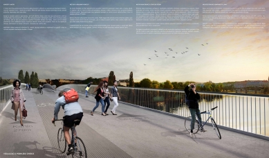
The bridge structure is monolithic, cast on a firm form (in situ) into an elegant shape that harmoniously complements the water surface. Exposed surfaces are treated with architectural concrete adorned with decorative elements. The undersides of the arches are illuminated by integrated LED strips.
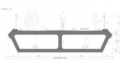
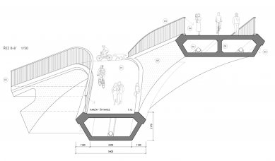
The walkable concrete surface, treated with pigment, creates a directionally divided space for pedestrians and cyclists. The roadway is illuminated by LED panels embedded in the railing. Part of the LED setup will include built-in shades to prevent glare for cyclists.
The railing, 1.3 m high, is made of corrosion-resistant stainless steel. The filling consists of vertical rods spaced 75 mm apart. The handrail will be made of a 150 mm wide profile of durable tropical wood to provide a comfortable surface for resting hands and elbows while contemplating the views of the river, the island, and other Prague bridges upstream.
STRUCTURAL SCHEME
Although the use of an arch structure with a top roadway is generally employed mainly for spanning deep valleys, and is therefore used quite atypically here, this design arises from the solutions of neighboring Prague bridges. The feasibility of the proposed structure was verified through static calculations.
Internal forces on the structure were examined using a plate-shell computational model in SCIA Engineer software utilizing the finite element method. The variable load due to pedestrian traffic was considered with a value of 5 kN/m2. The basic structural elements and their dimensions were statically verified in both ultimate states and meet the requirements set forth in a series of standards ČSN EN 1990—1992. Samples of outputs from the FEM model are part of the documentation.
FOUNDATION
A geological survey from 2016 describes the foundation conditions, which consist of sands and gravel-sandy sediments, along with a load-bearing layer of weathered Ordovician rocks, primarily slate at depths of 8 to 14 m below the surface. Groundwater in the foreland area is found at depths of 6 to 9 m below the surface.
The foundation of the bridge is assumed to be deep on reinforced concrete piles with a diameter of 1200 mm. The piles will be anchored into the load-bearing slate layer (Ordovician). The estimated load-bearing capacity of piles, which are 10 to 12 m long, is forecasted in the range of 5 to 6 MN. The pile material will withstand the environmental aggressiveness according to geotechnical and hydrogeological surveys (XA1 is anticipated). The piles are made of C25/30 concrete.
SUBSTRUCTURE
The substructure consists of massive reinforced concrete abutments made from C30/37 concrete, founded in sealed construction pits. Due to the nature of the substrate, it is not possible to assume full anchorage of the substructure in calculation models. The behavior of individual supports is considered semi-rigid in the models and will require more detailed investigation beyond this study.
LOAD-BEARING STRUCTURE
The dimensions of the load-bearing structure arise from the proposed static scheme and load-bearing and usability requirements, particularly regarding deflection limits due to variable loads. The load-bearing structure consists of two main supporting flat arches with spans of 165 m and 83 m, with hollow cross-sections made of reinforced concrete C40/50 (25 kN/m³). The arches are directly walkable at the apex. The central part of the bridge consists of a curved beam made of prestressed concrete, both in plan and elevation. The beam is anchored at the ends into the arches and, in the outer parts of the span, is supported by reinforced concrete walls. Along with the arches, this forms a rigid frame ensuring stability and minimizing the deflections of the arches. The prestressing will be implemented as additional into pre-prepared channels and anchorage blocks, followed by injection.
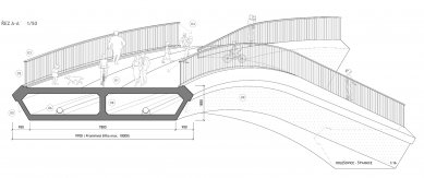
The cross-section of the load-bearing structure forms a trapezoidal chamber with variable height (1.5 m—3.0 m) and width (4.0 m—10.0 m), so as to respect both the architectural design and the static safety requirements of the structure. At the intersections of the load-bearing structure, a longitudinal rib is cast in place, connecting to a monolithic wall forming a frame corner. The thickness of the slab and walls of the chamber ranges from 300 to 500 mm.
Preliminary calculations were performed on a plate-shell model corresponding to the actual geometry of the proposed structure and to estimate the losses of prestressing due to rheological changes in the concrete. The calculations demonstrate that in the ultimate limit state, the compressive stresses will not exceed the limits defined by ČSN EN 1992 with a value of 0.6 fck (for concrete C40/50 corresponding to a limit of 24 MPa). All main load-bearing elements also comply with all standards set requirements for limiting tensile stresses.
At the place where the Vltava River washes the island of Štvanice and flows north towards the branching arms under the Libeň Bridge, it passes two significant districts – Holešovice and Karlín. The river flows under the arches of dozens of historical bridges, whose intersections inspired the design of this footbridge.
The design expresses humility towards the panorama that forms the city's identity: its lines are simple and modestly remain low above the horizon. However, it stands out with uncompromising engineering skill, allowing for a structure as slender as if it were just the imagined trajectory of a thrown pebble above the water. A single continuous arch spans the entire width of the riverbed, ensuring the structure’s resilience against floods. Neither this nor the two additional arches, transitioning into the pathway on Štvanice, disrupt the water flow.
We utilize the full potential of 21st-century engineering to make the arches as slender and flat as possible, ensuring the bridge ranks among the best contemporary structures in Europe.
URBAN AND LANDSCAPE CONTEXT
On the Holešovice side, the bank is reinforced against flooding with massive stone steps alongside dense native vegetation, returning to a more natural habitat and gently outlining the harsh environment of Holešovice with friendly greenery. Residents will be able to comfortably descend from the road level of the embankment directly to the river and to the HolKa P7 ferry stop.
We attribute an equal role to the island of Štvanice. Along the elegant arch of the footbridge to Karlín, a pair of arches on Štvanice slope down to the island using ramps with a gradient of less than 6% for very easy barrier-free access.
In Karlín, the footbridge leads into a smaller park sensitively designed among mature trees, creating an ideal meeting place for families and friends. At the same time, it connects to pedestrian pathways toward the interior of the district.
BRIDGE STRUCTURE AND STATIC SOLUTION
The dimensions of the supporting structure arise from the proposed static scheme and load-bearing requirements. The supporting structure consists of two main supporting flat arches with a hollow cross-section made of reinforced concrete. The arches are directly walkable at the apex. The central part of the bridge consists of a curved beam made of prestressed concrete, both in plan and elevation. The beam is anchored at the ends into the arches and supported at the outer parts of the span by reinforced concrete walls. The foundation of the bridge is deep on large-diameter piles. The design safely considers semi-rigid supports for the arches instead of fixed supports. The deep foundation is designed to achieve sufficient load-bearing capacity while also securing the structure against failures during potential floods.
The dimensions of the hollow structure allow for the revision of drains and repairs of the drainage system conducted within the cross-section, protected from atmospheric influences and vandalism.
To save on investment and operational costs, the entire structure is designed from concrete of standard strength class C40/50. High-quality concrete will effectively resist the predominant compressive stresses on the flat arches. The supporting structure is provided with waterproofing, and the walkable surface is composed of a concrete screed.
ARCHITECTURAL COMPONENTS OF THE FOOTBRIDGE
The bridge structure is monolithic, cast on a firm form (in situ) into an elegant shape that harmoniously complements the water surface. Exposed surfaces are treated with architectural concrete adorned with decorative elements. The undersides of the arches are illuminated by integrated LED strips.
The walkable concrete surface, treated with pigment, creates a directionally divided space for pedestrians and cyclists. The roadway is illuminated by LED panels embedded in the railing. Part of the LED setup will include built-in shades to prevent glare for cyclists.
The railing, 1.3 m high, is made of corrosion-resistant stainless steel. The filling consists of vertical rods spaced 75 mm apart. The handrail will be made of a 150 mm wide profile of durable tropical wood to provide a comfortable surface for resting hands and elbows while contemplating the views of the river, the island, and other Prague bridges upstream.
STRUCTURAL SCHEME
Although the use of an arch structure with a top roadway is generally employed mainly for spanning deep valleys, and is therefore used quite atypically here, this design arises from the solutions of neighboring Prague bridges. The feasibility of the proposed structure was verified through static calculations.
Internal forces on the structure were examined using a plate-shell computational model in SCIA Engineer software utilizing the finite element method. The variable load due to pedestrian traffic was considered with a value of 5 kN/m2. The basic structural elements and their dimensions were statically verified in both ultimate states and meet the requirements set forth in a series of standards ČSN EN 1990—1992. Samples of outputs from the FEM model are part of the documentation.
FOUNDATION
A geological survey from 2016 describes the foundation conditions, which consist of sands and gravel-sandy sediments, along with a load-bearing layer of weathered Ordovician rocks, primarily slate at depths of 8 to 14 m below the surface. Groundwater in the foreland area is found at depths of 6 to 9 m below the surface.
The foundation of the bridge is assumed to be deep on reinforced concrete piles with a diameter of 1200 mm. The piles will be anchored into the load-bearing slate layer (Ordovician). The estimated load-bearing capacity of piles, which are 10 to 12 m long, is forecasted in the range of 5 to 6 MN. The pile material will withstand the environmental aggressiveness according to geotechnical and hydrogeological surveys (XA1 is anticipated). The piles are made of C25/30 concrete.
SUBSTRUCTURE
The substructure consists of massive reinforced concrete abutments made from C30/37 concrete, founded in sealed construction pits. Due to the nature of the substrate, it is not possible to assume full anchorage of the substructure in calculation models. The behavior of individual supports is considered semi-rigid in the models and will require more detailed investigation beyond this study.
LOAD-BEARING STRUCTURE
The dimensions of the load-bearing structure arise from the proposed static scheme and load-bearing and usability requirements, particularly regarding deflection limits due to variable loads. The load-bearing structure consists of two main supporting flat arches with spans of 165 m and 83 m, with hollow cross-sections made of reinforced concrete C40/50 (25 kN/m³). The arches are directly walkable at the apex. The central part of the bridge consists of a curved beam made of prestressed concrete, both in plan and elevation. The beam is anchored at the ends into the arches and, in the outer parts of the span, is supported by reinforced concrete walls. Along with the arches, this forms a rigid frame ensuring stability and minimizing the deflections of the arches. The prestressing will be implemented as additional into pre-prepared channels and anchorage blocks, followed by injection.
The cross-section of the load-bearing structure forms a trapezoidal chamber with variable height (1.5 m—3.0 m) and width (4.0 m—10.0 m), so as to respect both the architectural design and the static safety requirements of the structure. At the intersections of the load-bearing structure, a longitudinal rib is cast in place, connecting to a monolithic wall forming a frame corner. The thickness of the slab and walls of the chamber ranges from 300 to 500 mm.
Preliminary calculations were performed on a plate-shell model corresponding to the actual geometry of the proposed structure and to estimate the losses of prestressing due to rheological changes in the concrete. The calculations demonstrate that in the ultimate limit state, the compressive stresses will not exceed the limits defined by ČSN EN 1992 with a value of 0.6 fck (for concrete C40/50 corresponding to a limit of 24 MPa). All main load-bearing elements also comply with all standards set requirements for limiting tensile stresses.
The English translation is powered by AI tool. Switch to Czech to view the original text source.

1 comment
add comment
Subject
Author
Date
...No, ...
šakal
30.01.18 06:07
show all comments