

Most Václava Rendera

Architectural Solution
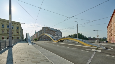
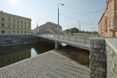
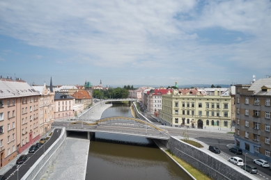
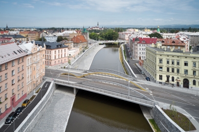
The construction of the bridge named after the significant Baroque creator from Olomouc, Václav Render, is part of a broader set of flood protection measures that increase the capacity of the Morava riverbed to the level of nearly a four-hundred-year flood through a regulated riverbed with new embankment walls and bridges.
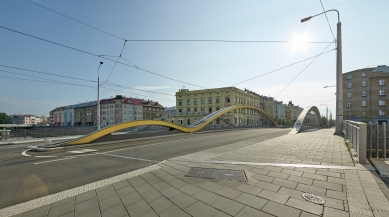
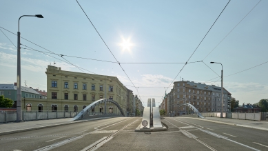
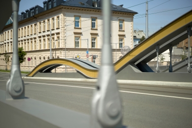
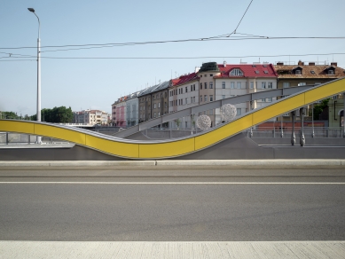
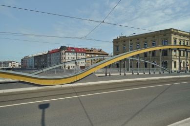
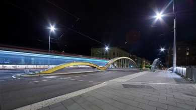
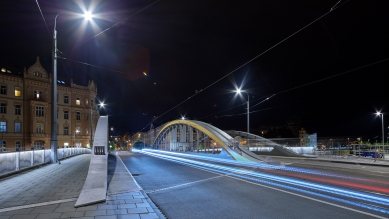
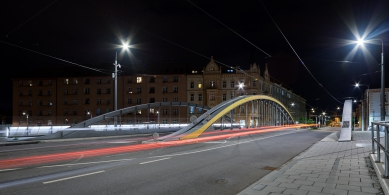
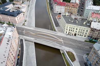
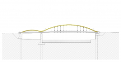
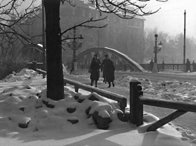
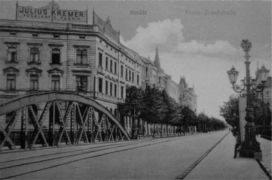
The design of the structural and architectural solution respects the context of the historical core of the Olomouc urban conservation area. It strives to suppress the traffic character of the construction and relates more to humans in its form and details than to cars or trams. The design draws its form from the historical bridge that stood at the site from the end of the 19th century until May 8, 1945. Thus, it serves as a certain form of allusion to this historical structure while not relinquishing its reference to the contemporary era. The arches indicate the structurality of the design through their tie rods, while the height profile of the arch beams is minimized. The lateral arches directly reference the riveted steel construction of the historical bridge with their longitudinal flanges and vertical connections. The central double-span arches are duplicated, thus dividing the bridge into two independent structural units, with their longitudinal arch line serving as a visual metaphor for movement across the river, transferring from one bank to another.
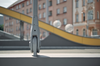
In connection with the construction's location in the historical center, attention was paid to mastering the details of the bridge structure, railings, and the lower part of the bridge structure over the pedestrian berm. The internal arches are lined with a golden cladding, which artistically highlights the flowing curve of the main steel bearing structure. Decorative elements are placed on the arches to prevent access. The railings along the sidewalks are designed as a prefabricated assembly of welded steel profiles with double-sided filling using stainless steel mesh and built-in sidewalk lighting.
Structural Solution
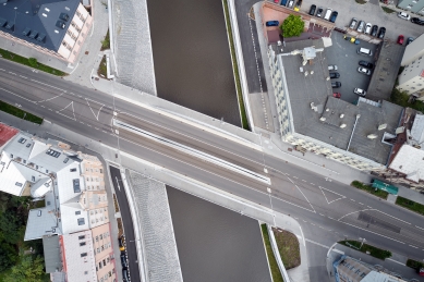
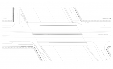
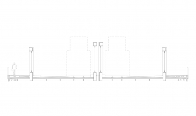
Due to the phased construction, the bridge consists of two structures, the left and the right. Statistically, it is a continuous beam with two spans for each structure and each of its main beams. The structure as a whole is obliquely placed on the abutments and the central support. The shorter span has a theoretical span of 14.2 m, the main span 38.3 m, and the total length of the bridge is 63.3 m. The entire bridge is 26.3 m wide. The outer beams are not reinforced with arches in the short span, while the arch in the long span has an absolute structural height of 4.835 m. The inner beams have an arch height of 2.48 m in the shorter span without hangers, and 5.585 m in the longer span. Hangers are used in all arches of longer spans. The main beams are formed by the outer longitudinal beams created from boxes with a variable cross-section, reinforced by an arch in the main span. The longitudinal beams have a constant cross-section of 1250 mm x 400 mm in the main span, while at the outer arches above the support, the cross-section changes to a welded box of 650 mm x 400 mm. The axial distance between the main beams is constant at 9,275 mm. The arches are designed from a closed welded profile measuring 500 mm x 600 mm. The cross-section is supplemented with internal reinforcements that pass outside the lower flange of the box at the location of the hangers. The main beams are connected by a system of crossbeams and longitudinal beams supporting the reinforced concrete deck and the tram track. Typical lower crossbeams and longitudinal beams are designed as welded I-profiles of variable height, with their lower faces aligned. Crossbeams above the abutments and supports are created by welding plates into a closed rectangular cross-section measuring 535 mm x 600 mm. Attached to the crossbeams on the outer side is a console supporting the pedestrian walkway.
Construction Execution
The assembly and also the extension took place in parts in the order of the right and left bridge structure. The choice of the extension principle in the longitudinal axis was influenced by the very restricted space at the abutment with dense development and the necessity to coordinate the work with the provisional tram operation. The structures were gradually assembled on assembly supports using mobile cranes from the level of the roadway. Before the extension commenced, the structure was partially fitted with formwork for the subsequent casting of the deck. After completing the assembly on the left bank, the structure was placed on sliding trolleys firmly connected to the supporting structure, which moved along the sliding track established at the assembly site. The beginning of the structure in the direction of extension was equipped with a long extending cantilever. The extension drive was ensured by a hydraulic pushing system anchored to the sliding track.
The construction of the bridge named after the significant Baroque creator from Olomouc, Václav Render, is part of a broader set of flood protection measures that increase the capacity of the Morava riverbed to the level of nearly a four-hundred-year flood through a regulated riverbed with new embankment walls and bridges.
The design of the structural and architectural solution respects the context of the historical core of the Olomouc urban conservation area. It strives to suppress the traffic character of the construction and relates more to humans in its form and details than to cars or trams. The design draws its form from the historical bridge that stood at the site from the end of the 19th century until May 8, 1945. Thus, it serves as a certain form of allusion to this historical structure while not relinquishing its reference to the contemporary era. The arches indicate the structurality of the design through their tie rods, while the height profile of the arch beams is minimized. The lateral arches directly reference the riveted steel construction of the historical bridge with their longitudinal flanges and vertical connections. The central double-span arches are duplicated, thus dividing the bridge into two independent structural units, with their longitudinal arch line serving as a visual metaphor for movement across the river, transferring from one bank to another.
In connection with the construction's location in the historical center, attention was paid to mastering the details of the bridge structure, railings, and the lower part of the bridge structure over the pedestrian berm. The internal arches are lined with a golden cladding, which artistically highlights the flowing curve of the main steel bearing structure. Decorative elements are placed on the arches to prevent access. The railings along the sidewalks are designed as a prefabricated assembly of welded steel profiles with double-sided filling using stainless steel mesh and built-in sidewalk lighting.
Structural Solution
Due to the phased construction, the bridge consists of two structures, the left and the right. Statistically, it is a continuous beam with two spans for each structure and each of its main beams. The structure as a whole is obliquely placed on the abutments and the central support. The shorter span has a theoretical span of 14.2 m, the main span 38.3 m, and the total length of the bridge is 63.3 m. The entire bridge is 26.3 m wide. The outer beams are not reinforced with arches in the short span, while the arch in the long span has an absolute structural height of 4.835 m. The inner beams have an arch height of 2.48 m in the shorter span without hangers, and 5.585 m in the longer span. Hangers are used in all arches of longer spans. The main beams are formed by the outer longitudinal beams created from boxes with a variable cross-section, reinforced by an arch in the main span. The longitudinal beams have a constant cross-section of 1250 mm x 400 mm in the main span, while at the outer arches above the support, the cross-section changes to a welded box of 650 mm x 400 mm. The axial distance between the main beams is constant at 9,275 mm. The arches are designed from a closed welded profile measuring 500 mm x 600 mm. The cross-section is supplemented with internal reinforcements that pass outside the lower flange of the box at the location of the hangers. The main beams are connected by a system of crossbeams and longitudinal beams supporting the reinforced concrete deck and the tram track. Typical lower crossbeams and longitudinal beams are designed as welded I-profiles of variable height, with their lower faces aligned. Crossbeams above the abutments and supports are created by welding plates into a closed rectangular cross-section measuring 535 mm x 600 mm. Attached to the crossbeams on the outer side is a console supporting the pedestrian walkway.
Construction Execution
The assembly and also the extension took place in parts in the order of the right and left bridge structure. The choice of the extension principle in the longitudinal axis was influenced by the very restricted space at the abutment with dense development and the necessity to coordinate the work with the provisional tram operation. The structures were gradually assembled on assembly supports using mobile cranes from the level of the roadway. Before the extension commenced, the structure was partially fitted with formwork for the subsequent casting of the deck. After completing the assembly on the left bank, the structure was placed on sliding trolleys firmly connected to the supporting structure, which moved along the sliding track established at the assembly site. The beginning of the structure in the direction of extension was equipped with a long extending cantilever. The extension drive was ensured by a hydraulic pushing system anchored to the sliding track.
Architects DRNH
The English translation is powered by AI tool. Switch to Czech to view the original text source.
0 comments
add comment