

<Mariánský most> translates to <Marian Bridge>

The Mariánský bridge was a significant step for our work, a step into a space that had been closed off and largely neglected in terms of architecture. Signals from the world and from the past, however, indicated that architecture and architects have something to contribute to bridge construction. It was difficult to overcome the misunderstanding and astonishment of those who were unable to accept the necessary level of influence that an architect has on the construction of this “purely technical” work.
In recent decades, there has been a prevailing opinion that bridges are built by “bridge builders” and “transport engineers,” and the architect has, at best, an advisory voice. We considered and continue to consider this opinion as misguided. The basic conceptual work, especially for urban bridges, must always be the work of an architect. From the primary discussion between the architect, the structural engineers, and the constructors, a system and geometry of the main structures must emerge, along with a detailed shape solution for most of the details. Ultimately, despite significant challenges, we succeeded in Ústí nad Labem. We prepared a spatial digital model of the bridge, which was subsequently transferred to static programs. The structural team also received the shape solution of the details in three-dimensional form and only finalised the precise sizing. Nonetheless, or perhaps precisely because of this, we managed to maintain not only the basic idea but also most of the individual elements in an acceptable form. A large construction brings great problems, but also many insights, especially regarding such an uncharted path as the birth of the Ústí bridge undoubtedly was. Perhaps this was precisely why the bridge was awarded the Prize from the European Association of Steel Structures in 1999.
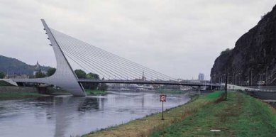
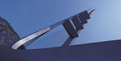
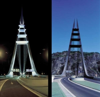
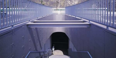
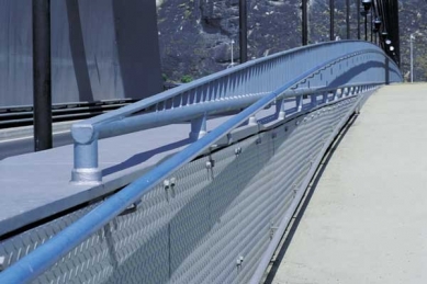
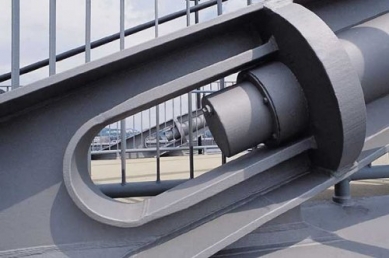
The new bridge had to cope with many limiting conditions and influences. The relatively wide river and the narrow transport corridor on the left bank under the Mariánská rock are just some of them. The Elbe enters the city's territory almost exactly from the north. In close proximity to the center, it sharply turns over 90° to the east. This naturally caused the river to be significantly deeper and faster on the left bank. Logically, the navigation channel also runs through here. On the right bank, there are shallows from sediment and a significantly smaller current. We wanted to build the bridge's pylon as a counterbalance to the rock, and aside from the fact that there was no room for it on the left bank, the fact of the smaller depth and calmer waters was one of the main reasons for placing the pylon here. It could stand up to the bank, but with the increasing span, its height would increase as well. Thus, we sought the ideal location between the total length of the necessary span, the dimensions of the navigation profile, the height of the pylon and main supporting beam, the distance from the bank, and the depth and current of the river. The bridge's structure tightly envelops the navigation profile, both at the Ústí support and at the right bank, where the feet of the pylon touch it closely. The main suspended span is 120 m long, and the auxiliary span is 60 m. From the very beginning of our considerations, this shorter part of the bridge has been a kind of fixed stabilizing element that, with its volume, not only manages to transfer the load of the main span and compositionally balances the mass of the rock and the sharp turn of the river but will also serve as a platform from which the entire bridge can be assembled. The confined conditions on the left bank almost to the centimeter determined the exact position of the bridge. The distances between two crossings to Ústí and Krásné Březno and the minimum lengths of the splays before the bridge entrances defined the maximum possible lengths of the ramps. Their maximum allowable slope, in turn, influenced the upper level of the bridge deck. The navigation profile limited the lower boundary of the structure. The result was a very small structural height. This, along with the length of the span, clearly spoke in favor of the suspended bridge system. A single-chamber elevated central truss carries roughly 11 m long cantilevers with an orthotropic deck. Thus, the roadways of the bridge are at a height that allows for easy connection to the ramps. The ramps connect to the embankment road in the middle between both directions. This arrangement is spatially the most advantageous; however, it was necessary to build new railway and bank walls. To obtain enough space for the traffic solution on the left bank without encroaching too much into the river, we had to modify and move the railing wall of the railway. This was associated with considerable technical problems, as it was not possible to interrupt traffic on this busy line. The new wall is made of concrete and is divided by a system of rectangular expansion joints and seals. Its very dark color is intended to blend in with the mass of the Mariánská rock above it. The bank wall on the left bank is also new, but unfortunately, it was not realized according to our design. On the left bank, there is a line of trees between the sidewalk and the bicycle path. Low trimmed bushes, intended to shield the benches on the bank from road traffic, however, were not planted. Also, other details that make the bank a promenade are unfortunately missing. The driving lane at Krásné Březno passes under the bridge. The passing profile of the embankment road, dimensioned for large trucks and trolleybuses, was so high that it was necessary to lower the level of the road below the level of the bank wall to approximately the water level for a ten-year flood. The situation here is similar to that of the Dr. Edvard Beneš bridge, except that there, this part of the roadway is even much lower and is thus flooded earlier and more often. The new bridge is designed for a hundred-year flood, and in the case of smaller floods, the upper part of the bank road towards Krásné Březno will function in both directions. The left bank ramps are essentially a separate bridge. They are 150 m long with a fixed point at the axis of the main bridge. They dilate on thin pillars towards both ends. They have a reinforced concrete composite deck on a steel truss with cantilevers. Only a short section of the ramps is concrete just above the ground. On the right bank, the bridge connects to the existing viaduct to Kamenný vrch. We only adjusted the connecting and access ramps to minimize the non-buildable “residual” spaces throughout the area and, conversely, to prepare interesting sites for further potential investments. The right bank, aside from the repairs of the bank wall and several parts of the sidewalks, remained unchanged. Under the bridge on the right bank, there is a walking and cycling path that should lead from Ústí to Děčín and further to the German border. Therefore, we wanted to embed space for a café or restaurant into the embankment of the bank support to create an interesting, attractive point on this route. However, the intention could not be realized. The outermost field of the pylon extends over the right bank mainly because the central sewer collector runs to the wastewater treatment plant here. The lower part of the pylon in the river is concrete. Above the five-year water level, the pylon is steel and passable, allowing access for anchoring cables and other inspections via internal ladders. The entire main span of the bridge is also made of steel. In contrast, the deck of the shorter auxiliary span is reinforced concrete between the parapet beams. Its weight thus helps to bear the load from the main span and eliminates negative reactions at the right bank support. The height of the pylon was determined by the span of the main span. The distance between its two walls was set by the passing profiles on the bridge. The pulling of the legs under the bridge deck required a hydrostatic calculation. If there are two obstacles in the river at a small distance from one another, the water between them creates a strong whirlpool that accumulates layers of sediment behind the first obstacle and undermines the second. Thus, it was necessary to pull both legs of the pylon together so that they behaved as much as possible like a single mass against the water. Additionally, their outline had to create an acceptable streamlined shape in the water, even though the entire pylon does not stand in the direction of the current. The legs are concrete and have a common concrete foundation. The bending stresses that the compression of the legs into the pylon introduced are eliminated by the shape of the legs and a strong crossbeam at the level of the bridge deck. Bends at the top of the pylon from the loading of the cables are transferred by four crossbeams in the shape of aerodynamic wings that connect both parts of the pylon at the points where the cables are suspended. It took a long time to shape the rear curves of the pylon. Their approaching and distancing from the front edge changed based on the static calculations and the construction needs of the bridge. Eventually, they stabilized into the form of empirical curves constructed in a ratio of 1: 3. The sidewalk for pedestrians and cyclists is in the middle of the bridge, on the upper surface of the central truss. Above the vertical walls of the beam, there is an anchoring system for fifteen pairs of cables that spread into two parabolic planes. The anchors are above the truss along with all technical details for cable attachment. We wanted to give pedestrians the possibility to “touch” the forces that support the entire bridge and to highlight the structural details. The required static height of the main beam and the space between the hangers protect pedestrians and separate the sidewalk from the roadways. The sidewalk is not between cars but above them, offering views of the city and the river while being safely separated from traffic. However, it was necessary to descend with the sidewalk to the bank from a greater height than is the case with roads. On the left bank, there is a staircase with a platform for the disabled, which passes just before the left bank splay through the main support beam and the bank support and lands on the sidewalk at the bank. On the right bank, there is a ramp that descends into a passage in the embankment. The railing at the edge of the bridge is designed for 100 tons of lateral impact. Three strong pipes reinforced with longitudinal strips support the railings, shaping and constructing the cantilevers of the bridge deck. Four brackets under the wide handle complete the railing and conduct light from lamps in the supporting columns. At the edge of the bridge, a guiding line of light appears in both directions. The main bridge has a fixed point where the main span connects to the pylon and dilates towards both bank supports. The gray concrete of the lower parts of the structure and two shades of silvery gray of the steel structures are complemented by the blue accent of the four wings of the pylon and the line of the railing handle. The coloration is very simple, primarily so as not to overshadow the intrinsic shaping of the structures. The roadways and the sidewalk are illuminated by a series of lamps from the company Bega. The lighting in the brackets of the railing and the spotlights of the festive lighting also come from the same company. The external outline of the pylon, silhouetted against the sky during the day, is completely suppressed under the night lighting. In contrast, the internal surfaces of the pylon and the parabolic planes of the cables glow significantly. When the bridge is festively lit, a beam of light emanates from the top of the pylon towards the gilded dome of the Baroque tower of the Střekov church. From there, it was supposed to reflect back to the Edvard Beneš bridge, but this could not be realized.
The deep riverbed and the city cramped between the steep slopes of the surrounding hills. The transport corridor of the road and the railway is squeezed into a narrow strip of embankment under the rock. Ústí, Krásné Březno, Střekov. The Mariánská rock, Kamenný vrch, and Větruše. Three cities, three hills, and between them a river with two bridges. A road bridge and a railway bridge. It is necessary to find a place for a third bridge. The bend of the river under the Mariánská rock is located midway between the centers of Ústí and Krásné Březno. On the opposite bank ends a busy road from the Střekov housing estate at Kamenný vrch with a sharp loop. The Edvard Beneš bridge is so close that a new bridge can easily take on part of its traffic load and, if necessary, replace it. And yet, it is far enough away for the additional span to complement the natural, regular rhythm of the previous bridges. Here is the right place for a new bridge. At the edge of the port spit, directly opposite the rock. The extended axis of the new bridge, like the axis of the Edvard Beneš bridge, points to the tower of the Church of the Holy Trinity in Střekov.
A rectangle of trusses, a steel arch, and a suspended triangle. The nineteenth, twentieth, and twenty-first centuries. Each of Ústí's bridges has its uniqueness, its history; each is a reflection of its time. The Ústí bridges are expressions of a confident, rich city.
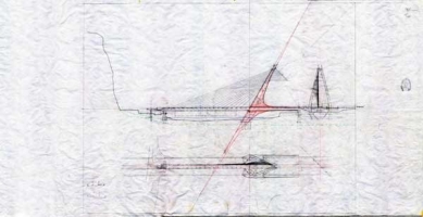
The strength of the magical equilateral triangle and the third division permeates the entire basic geometric construction. The length of the bridge, 198 m, is divided into 3 x 60 m + 3 x 6 m. The angle of inclination of the pylon at 60 degrees also derives from the construction of the equilateral triangle. The vertical line from the extended line of the pylon's inclination over the length of the main span, confirms the delimitation of the end of the shorter span. This length also determines the construction of the upper and lower rear curves of the pylon. Both are constructed as empirical curves in a ratio of 1: 3, which is the relationship between the height of the equilateral triangle and half of its base, or also the relationship between the distance from the peak to the centroid with the side of the same triangle. Further minor divisions come from the basic six-meter module and its divisions and multiplications. All elements of the supporting structure and individual details are subordinated to this. The cables support the beam at intervals of 6 m and begin 3 x 6 m from the Ústí support and the main point of the pylon. The fastening of the cables on the pylon is defined by half the side of the equilateral triangle with an edge of 60 m. The perpendicular height of the pylon above the bridge deck is also 60 m.
The dimensions of the pylon of the bridge, the youngest major construction in the city, are comparable to the oldest urban construction, the Gothic Church of the Assumption of the Virgin Mary. In both the transverse and longitudinal views, it is possible to inscribe the outlines of the church into the inner space of the pylon. After the patroness of this church, the city, and the rock, the new bridge was named Mariánský.
First, a construction peninsula was brought into the river, to the place where the pylon was to stand. In its center, a pit was enclosed by Milanese walls, anchoring piles were drilled into its bottom, and with a dense network of reinforcements, the foundation of the pylon was cast. Large parts of complex wooden formwork defined the shape of the legs of the pylon. After their concrete pouring, the actual assembly began. Large pieces of steel structure were delivered from the bridge factory by trucks. Individual parts of the construction were gradually assembled with the help of cranes. At the moment when about two-thirds of the pylon were completed, the main span of the bridge was extended. A steel truss along with a larger portion of the cantilevers was assembled on the reinforced concrete deck of the secondary span of the bridge and on the adjacent part of the foreland, and moved across the river on three temporary supports on the launching track. The initial phases of the design assumed a cantilever assembly from the Střekov bank, gradually suspending individual segments on the cables. Unfortunately, the change in construction technology necessitated the required over-dimensioning of the supporting beam, which had to bear the load of the assembly conditions before suspension. After being lowered onto the bearings of the Ústí support and connecting to the pylon, it was possible to complete the remaining parts of the pylon, remove the temporary supports, tension the cables, and finalize the bridge. Parallel to the construction of the main bridge, work was also in progress on the bank and railway walls, supports, and splays of both forelands.
In recent decades, there has been a prevailing opinion that bridges are built by “bridge builders” and “transport engineers,” and the architect has, at best, an advisory voice. We considered and continue to consider this opinion as misguided. The basic conceptual work, especially for urban bridges, must always be the work of an architect. From the primary discussion between the architect, the structural engineers, and the constructors, a system and geometry of the main structures must emerge, along with a detailed shape solution for most of the details. Ultimately, despite significant challenges, we succeeded in Ústí nad Labem. We prepared a spatial digital model of the bridge, which was subsequently transferred to static programs. The structural team also received the shape solution of the details in three-dimensional form and only finalised the precise sizing. Nonetheless, or perhaps precisely because of this, we managed to maintain not only the basic idea but also most of the individual elements in an acceptable form. A large construction brings great problems, but also many insights, especially regarding such an uncharted path as the birth of the Ústí bridge undoubtedly was. Perhaps this was precisely why the bridge was awarded the Prize from the European Association of Steel Structures in 1999.
The new bridge had to cope with many limiting conditions and influences. The relatively wide river and the narrow transport corridor on the left bank under the Mariánská rock are just some of them. The Elbe enters the city's territory almost exactly from the north. In close proximity to the center, it sharply turns over 90° to the east. This naturally caused the river to be significantly deeper and faster on the left bank. Logically, the navigation channel also runs through here. On the right bank, there are shallows from sediment and a significantly smaller current. We wanted to build the bridge's pylon as a counterbalance to the rock, and aside from the fact that there was no room for it on the left bank, the fact of the smaller depth and calmer waters was one of the main reasons for placing the pylon here. It could stand up to the bank, but with the increasing span, its height would increase as well. Thus, we sought the ideal location between the total length of the necessary span, the dimensions of the navigation profile, the height of the pylon and main supporting beam, the distance from the bank, and the depth and current of the river. The bridge's structure tightly envelops the navigation profile, both at the Ústí support and at the right bank, where the feet of the pylon touch it closely. The main suspended span is 120 m long, and the auxiliary span is 60 m. From the very beginning of our considerations, this shorter part of the bridge has been a kind of fixed stabilizing element that, with its volume, not only manages to transfer the load of the main span and compositionally balances the mass of the rock and the sharp turn of the river but will also serve as a platform from which the entire bridge can be assembled. The confined conditions on the left bank almost to the centimeter determined the exact position of the bridge. The distances between two crossings to Ústí and Krásné Březno and the minimum lengths of the splays before the bridge entrances defined the maximum possible lengths of the ramps. Their maximum allowable slope, in turn, influenced the upper level of the bridge deck. The navigation profile limited the lower boundary of the structure. The result was a very small structural height. This, along with the length of the span, clearly spoke in favor of the suspended bridge system. A single-chamber elevated central truss carries roughly 11 m long cantilevers with an orthotropic deck. Thus, the roadways of the bridge are at a height that allows for easy connection to the ramps. The ramps connect to the embankment road in the middle between both directions. This arrangement is spatially the most advantageous; however, it was necessary to build new railway and bank walls. To obtain enough space for the traffic solution on the left bank without encroaching too much into the river, we had to modify and move the railing wall of the railway. This was associated with considerable technical problems, as it was not possible to interrupt traffic on this busy line. The new wall is made of concrete and is divided by a system of rectangular expansion joints and seals. Its very dark color is intended to blend in with the mass of the Mariánská rock above it. The bank wall on the left bank is also new, but unfortunately, it was not realized according to our design. On the left bank, there is a line of trees between the sidewalk and the bicycle path. Low trimmed bushes, intended to shield the benches on the bank from road traffic, however, were not planted. Also, other details that make the bank a promenade are unfortunately missing. The driving lane at Krásné Březno passes under the bridge. The passing profile of the embankment road, dimensioned for large trucks and trolleybuses, was so high that it was necessary to lower the level of the road below the level of the bank wall to approximately the water level for a ten-year flood. The situation here is similar to that of the Dr. Edvard Beneš bridge, except that there, this part of the roadway is even much lower and is thus flooded earlier and more often. The new bridge is designed for a hundred-year flood, and in the case of smaller floods, the upper part of the bank road towards Krásné Březno will function in both directions. The left bank ramps are essentially a separate bridge. They are 150 m long with a fixed point at the axis of the main bridge. They dilate on thin pillars towards both ends. They have a reinforced concrete composite deck on a steel truss with cantilevers. Only a short section of the ramps is concrete just above the ground. On the right bank, the bridge connects to the existing viaduct to Kamenný vrch. We only adjusted the connecting and access ramps to minimize the non-buildable “residual” spaces throughout the area and, conversely, to prepare interesting sites for further potential investments. The right bank, aside from the repairs of the bank wall and several parts of the sidewalks, remained unchanged. Under the bridge on the right bank, there is a walking and cycling path that should lead from Ústí to Děčín and further to the German border. Therefore, we wanted to embed space for a café or restaurant into the embankment of the bank support to create an interesting, attractive point on this route. However, the intention could not be realized. The outermost field of the pylon extends over the right bank mainly because the central sewer collector runs to the wastewater treatment plant here. The lower part of the pylon in the river is concrete. Above the five-year water level, the pylon is steel and passable, allowing access for anchoring cables and other inspections via internal ladders. The entire main span of the bridge is also made of steel. In contrast, the deck of the shorter auxiliary span is reinforced concrete between the parapet beams. Its weight thus helps to bear the load from the main span and eliminates negative reactions at the right bank support. The height of the pylon was determined by the span of the main span. The distance between its two walls was set by the passing profiles on the bridge. The pulling of the legs under the bridge deck required a hydrostatic calculation. If there are two obstacles in the river at a small distance from one another, the water between them creates a strong whirlpool that accumulates layers of sediment behind the first obstacle and undermines the second. Thus, it was necessary to pull both legs of the pylon together so that they behaved as much as possible like a single mass against the water. Additionally, their outline had to create an acceptable streamlined shape in the water, even though the entire pylon does not stand in the direction of the current. The legs are concrete and have a common concrete foundation. The bending stresses that the compression of the legs into the pylon introduced are eliminated by the shape of the legs and a strong crossbeam at the level of the bridge deck. Bends at the top of the pylon from the loading of the cables are transferred by four crossbeams in the shape of aerodynamic wings that connect both parts of the pylon at the points where the cables are suspended. It took a long time to shape the rear curves of the pylon. Their approaching and distancing from the front edge changed based on the static calculations and the construction needs of the bridge. Eventually, they stabilized into the form of empirical curves constructed in a ratio of 1: 3. The sidewalk for pedestrians and cyclists is in the middle of the bridge, on the upper surface of the central truss. Above the vertical walls of the beam, there is an anchoring system for fifteen pairs of cables that spread into two parabolic planes. The anchors are above the truss along with all technical details for cable attachment. We wanted to give pedestrians the possibility to “touch” the forces that support the entire bridge and to highlight the structural details. The required static height of the main beam and the space between the hangers protect pedestrians and separate the sidewalk from the roadways. The sidewalk is not between cars but above them, offering views of the city and the river while being safely separated from traffic. However, it was necessary to descend with the sidewalk to the bank from a greater height than is the case with roads. On the left bank, there is a staircase with a platform for the disabled, which passes just before the left bank splay through the main support beam and the bank support and lands on the sidewalk at the bank. On the right bank, there is a ramp that descends into a passage in the embankment. The railing at the edge of the bridge is designed for 100 tons of lateral impact. Three strong pipes reinforced with longitudinal strips support the railings, shaping and constructing the cantilevers of the bridge deck. Four brackets under the wide handle complete the railing and conduct light from lamps in the supporting columns. At the edge of the bridge, a guiding line of light appears in both directions. The main bridge has a fixed point where the main span connects to the pylon and dilates towards both bank supports. The gray concrete of the lower parts of the structure and two shades of silvery gray of the steel structures are complemented by the blue accent of the four wings of the pylon and the line of the railing handle. The coloration is very simple, primarily so as not to overshadow the intrinsic shaping of the structures. The roadways and the sidewalk are illuminated by a series of lamps from the company Bega. The lighting in the brackets of the railing and the spotlights of the festive lighting also come from the same company. The external outline of the pylon, silhouetted against the sky during the day, is completely suppressed under the night lighting. In contrast, the internal surfaces of the pylon and the parabolic planes of the cables glow significantly. When the bridge is festively lit, a beam of light emanates from the top of the pylon towards the gilded dome of the Baroque tower of the Střekov church. From there, it was supposed to reflect back to the Edvard Beneš bridge, but this could not be realized.
The deep riverbed and the city cramped between the steep slopes of the surrounding hills. The transport corridor of the road and the railway is squeezed into a narrow strip of embankment under the rock. Ústí, Krásné Březno, Střekov. The Mariánská rock, Kamenný vrch, and Větruše. Three cities, three hills, and between them a river with two bridges. A road bridge and a railway bridge. It is necessary to find a place for a third bridge. The bend of the river under the Mariánská rock is located midway between the centers of Ústí and Krásné Březno. On the opposite bank ends a busy road from the Střekov housing estate at Kamenný vrch with a sharp loop. The Edvard Beneš bridge is so close that a new bridge can easily take on part of its traffic load and, if necessary, replace it. And yet, it is far enough away for the additional span to complement the natural, regular rhythm of the previous bridges. Here is the right place for a new bridge. At the edge of the port spit, directly opposite the rock. The extended axis of the new bridge, like the axis of the Edvard Beneš bridge, points to the tower of the Church of the Holy Trinity in Střekov.
A rectangle of trusses, a steel arch, and a suspended triangle. The nineteenth, twentieth, and twenty-first centuries. Each of Ústí's bridges has its uniqueness, its history; each is a reflection of its time. The Ústí bridges are expressions of a confident, rich city.
The strength of the magical equilateral triangle and the third division permeates the entire basic geometric construction. The length of the bridge, 198 m, is divided into 3 x 60 m + 3 x 6 m. The angle of inclination of the pylon at 60 degrees also derives from the construction of the equilateral triangle. The vertical line from the extended line of the pylon's inclination over the length of the main span, confirms the delimitation of the end of the shorter span. This length also determines the construction of the upper and lower rear curves of the pylon. Both are constructed as empirical curves in a ratio of 1: 3, which is the relationship between the height of the equilateral triangle and half of its base, or also the relationship between the distance from the peak to the centroid with the side of the same triangle. Further minor divisions come from the basic six-meter module and its divisions and multiplications. All elements of the supporting structure and individual details are subordinated to this. The cables support the beam at intervals of 6 m and begin 3 x 6 m from the Ústí support and the main point of the pylon. The fastening of the cables on the pylon is defined by half the side of the equilateral triangle with an edge of 60 m. The perpendicular height of the pylon above the bridge deck is also 60 m.
The dimensions of the pylon of the bridge, the youngest major construction in the city, are comparable to the oldest urban construction, the Gothic Church of the Assumption of the Virgin Mary. In both the transverse and longitudinal views, it is possible to inscribe the outlines of the church into the inner space of the pylon. After the patroness of this church, the city, and the rock, the new bridge was named Mariánský.
First, a construction peninsula was brought into the river, to the place where the pylon was to stand. In its center, a pit was enclosed by Milanese walls, anchoring piles were drilled into its bottom, and with a dense network of reinforcements, the foundation of the pylon was cast. Large parts of complex wooden formwork defined the shape of the legs of the pylon. After their concrete pouring, the actual assembly began. Large pieces of steel structure were delivered from the bridge factory by trucks. Individual parts of the construction were gradually assembled with the help of cranes. At the moment when about two-thirds of the pylon were completed, the main span of the bridge was extended. A steel truss along with a larger portion of the cantilevers was assembled on the reinforced concrete deck of the secondary span of the bridge and on the adjacent part of the foreland, and moved across the river on three temporary supports on the launching track. The initial phases of the design assumed a cantilever assembly from the Střekov bank, gradually suspending individual segments on the cables. Unfortunately, the change in construction technology necessitated the required over-dimensioning of the supporting beam, which had to bear the load of the assembly conditions before suspension. After being lowered onto the bearings of the Ústí support and connecting to the pylon, it was possible to complete the remaining parts of the pylon, remove the temporary supports, tension the cables, and finalize the bridge. Parallel to the construction of the main bridge, work was also in progress on the bank and railway walls, supports, and splays of both forelands.
The English translation is powered by AI tool. Switch to Czech to view the original text source.
1 comment
add comment
Subject
Author
Date
A statik?
ing.
12.02.19 11:02
show all comments