KI Aula – non-traditional use of glued laminated timber

Publisher
Tisková zpráva
11.06.2012 11:45
TAROS NOVA s.r.o.

Gert Wingårdh

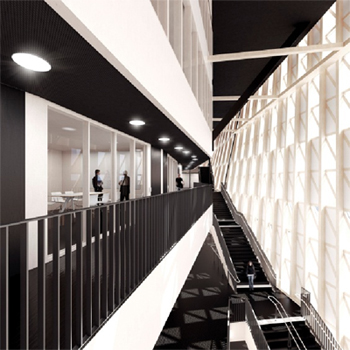
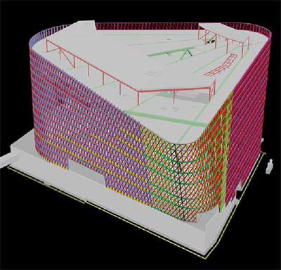
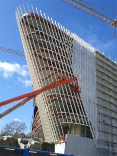
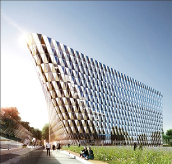
Visualization of the auditorium building
Architect:
Gert Wingardh
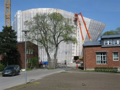
Investor: Karolinska Hus, Stockholm, SE
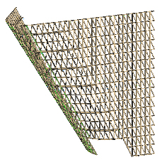
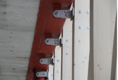
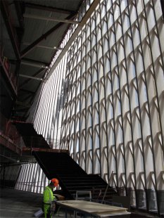
Static analysis of the cladding: STATIKA Engineering Office s.r.o., Liberec
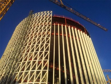
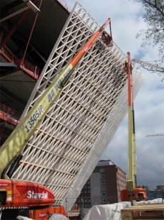
Design, supply and installation of wooden structure: TAROS NOVA s.r.o., Rožnov pod Radhoštěm
Design, supply and installation of facade: Fenestra Wieden s.r.o.
Manufacturer of glued laminated timber: MM Kaufmann Reuthe, AT
Implementation period: 2011-2013


Interior visualization
In the Swedish city of Solna, which is part of the agglomeration around the capital Stockholm, a campus of one of the most significant medical universities in Europe – Karolinska Institutet – is currently being established. This complex will include university buildings, a new hospital, a science park, and a new auditorium building. In the future, it will be used not only for academic purposes and scientific symposiums but also for an event of global significance – the awarding of Nobel Prizes in Medicine and Physiology. The architectural design was developed by a prominent architectural firm led by the renowned Swedish architect Gert Wingårdh. Glued laminated timber is used as the load-bearing structure of the outer shell for the façade system made of aluminum profiles. This combination is very atypical, and in such a scope, it represents a unique system. For this reason, close cooperation between the architectural office, design, and implementation companies was necessary from the very beginning of the project documentation process. The final project and technical solution is the result of the joint effort of all involved parties. The company TAROS NOVA s.r.o. participated in the project as the designer and supplier of the wooden structure.

Description of the building

Complete 3D model of the structure
The basic shape of the entire building can be described as a three-sided prism with rounded corners. One corner significantly leans out into the exterior, and at the most inclined point, the parapet projects almost 18 m above the terrain. Between the vertical and leaning parts, the columns gradually deviate from the vertical both radially and tangentially concerning the plane of the shell. In this part, the building has the shape of a distorted planar surface. The perimeter of the building at the level of the terrain is 180 m, due to the inclination, at the highest point of the parapet, the perimeter increases to 200 m. The height of the entire eight-story building reaches 32.5 m. The building’s structure is made of steel with a concrete stiffening core. The ceiling structures are made of prestressed concrete panels.

Wooden structure

The load-bearing structure of the façade is designed as a self-supporting wooden frame, which forms a spatial shell around the entire perimeter of the building. This shell consists of linear elements that can be divided into three basic groups. The main load-bearing elements consist of vertical columns. At the points of the distorted surface, they gradually lean out, and in the most projecting parts, their tilt reaches the angle of inclination of the diagonal elements. The base profile of these columns is 120/200. In places where these columns span larger distances, they have a larger cross-section, with the largest dimension being 140/400. The spacing of the columns is 900 mm. In the inclined part, this spacing increases vertically. The columns are continuous and form the main load-bearing element that transfers the vertical loads of the outer shell.
Part of 3D model for wooden structure production
The primary horizontal elements are battens with a profile of 120/120. In areas where the wooden structure of the façade connects to the steel main structure of the building, the battens have the same width as the column. The mutual spacing of the battens is 1800 mm. The last part of this grid consists of diagonal elements with a profile of 120/120. The battens and diagonals are made from short pieces inserted between the columns.
In the most open spaces, the columns span nearly 20 m. In this area, due to significant deflections of the columns, a horizontal beam is installed to provide additional support to the columns in the horizontal direction. Horizontal reactions from the wind are transmitted from the columns through this beam and six supports to the steel structure.
To connect the individual parts of the columns, bolted and doweled joints with an internal steel plate are used. The fastening of the battens and diagonals is solved using screws. All joints are designed with the aim of minimizing visibility. Most joints are executed from the external non-visible side, with only the heads of the screws fastening the diagonals being visible. In some parts of the structure, greater tensile forces occur in the battens. These forces cannot be transferred by screws; therefore, in these parts, the battens had to be additionally reinforced with a steel strap that transmits all tensile forces. Compressive forces are transmitted through the contact area between the batten and the column.
Almost 400 m3 of glued laminated timber of strength classes GL24h and GL28c is used in the entire structure. In total, there are 7200 pieces of wooden elements, of which nearly 3000 are unique. Such a quantity of individual elements is due to the inclination of the columns; in the leaning part, each element is original. The length and angle of the end cut of individual elements vary. The number of atypical pieces necessitates the use of specialized software connected to CNC machining centers. A comprehensive 3D model of the entire structure was used to create the 3D model of all the wooden elements. This model contained all structural elements and allowed for collision checking with other parts. The wooden elements are finished with a white coating. The entire inner side of the cladding is visible. During the application of coatings, it is necessary to exercise increased caution, as well as during assembly, to avoid damaging the visually exposed areas.

Anchoring of the structure

In the upper floors of the building, there will be relatively large vertical deflections, and it is necessary to ensure that the anchoring is independent in the vertical direction. All vertical loads are transmitted through the columns to the base anchors. The fastening of the outer shell to the main structure is solved by anchoring the columns to the steel structure. The anchoring must transfer horizontal loads and allow for dilation of the main structure so that there is no additional force transfer between the wooden grid and the steel structure of the building. In most of the building, the anchors transfer only the loads in the plane perpendicular to the shell; however, in the leaning part, it is also necessary to ensure the transfer of forces in the plane parallel to the shell. The anchors are designed to be adjustable in all directions to ensure precise placement of the columns. Visible elements of the anchors will be hidden in the ceiling after the construction is completed.

Assembly of the structure

The wooden structure of the outer shell has high requirements for assembly accuracy since it forms the underlying grid for the façade system made of aluminum profiles, insulating triple glazing, and vacuum panels. These are prefabricated, and therefore it is necessary to maintain deviations between individual elements within 5 mm. It was also necessary to consider temperature changes during assembly and volume changes due to moisture fluctuations throughout the life of the structure.
The entire construction assembly was divided into several phases. As the first step, parts of the anchors had to be welded to the main steel structure, to which the wooden columns will be connected by means of connecting pieces. Because the accuracy requirements for the outer shell are higher than for the steel structure, it was necessary to geodetically mark points for the welding of the anchors. In the curved sections, it was necessary to establish points for each anchoring location. For this purpose, nearly 1300 points were marked to serve for welding the steel anchoring elements. The counterparts of the anchors were installed in pre-drilled holes and notches in the columns and were connected during assembly using adjustable elements with the parts welded to the steel structure. The use of precise machine processing allowed the use of carpentry joints to facilitate assembly. The columns are machined with grooves into which battens, fitted with pins on the ends, were inserted from the outer side. The entire connection is secured on the exterior side with screws. This solution significantly speeds up assembly and increases accuracy. The diagonal, which is positioned between the batten and column, requires no special processing and is only secured with screws. This system allows for relatively rapid assembly progress.
Great attention was paid to the protection of the structure. The wooden elements are covered with a tarp from the outside against the effects of the weather. On the inside, the elements were protected by wrapping to prevent damage from other trades during construction. Due to the high precision in manufacturing and assembly, the entire structure was successfully enclosed and remained within the allowed tolerances.

Conclusion

The wooden structure is now completed. The assembly of aluminum profiles and glazing will take place until the end of September. The entire building will be officially opened in May 2013.
Glued laminated timber, due to its variability and processability, creates structural elements with high aesthetic value. Modern technology allows for the gluing of spatial shapes and precise machine processing. Thanks to its properties, wood is returning to areas from which it was previously entirely displaced by steel and concrete.

Author: Jan Valíček
The English translation is powered by AI tool. Switch to Czech to view the original text source.
0 comments
add comment

Related articles